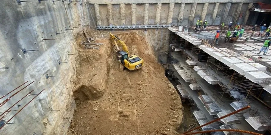
The most expensive mistake we see in Oxnard is a contractor assuming a standard shoring plan from Los Angeles will work here. It won't. The Oxnard Plain sits on a stacked sequence of Holocene alluvium—interbedded clays, silts, and loose sands—with groundwater often less than 8 feet below grade. A 25-foot excavation near the old sugar beet factory experienced base heave during dewatering because the design didn't account for the low undrained shear strength of the upper Bay Mud layer. Our design approach starts with a thorough subsurface investigation, often integrating CPT soundings to map the stratigraphy continuously. For cuts deeper than 15 feet, we pair those results with a slope stability analysis to verify global factors of safety before selecting a shoring system. Every design we produce is stamped by a California-licensed geotechnical engineer.
On the Oxnard Plain, your excavation design lives or dies by the groundwater table you assume in the model.
Our approach and scope
Oxnard's climate isn't just about strawberries—the persistent marine layer and the Oxnard Plain aquifer create a permanently high groundwater condition that dominates excavation design. Unlike inland sites where dewatering is seasonal, any cut deeper than 10 feet here requires a permanent dewatering and recharge plan approved by the Fox Canyon Groundwater Management Agency. We design the excavation support system as a complete package: the wall, the bracing, and the hydraulic control. For stiff inclusions in soft clay, stone columns can improve the passive resistance zone ahead of the wall toe, reducing embedment depth requirements. Our calculations follow AASHTO LRFD principles for structural elements, but we switch to ASD for global stability checks—a deliberate choice to avoid unconservative outcomes in these sensitive soils. Material parameters come from our in-house triaxial and consolidation testing program, never from generic correlations.
Common questions
What is the typical cost range for a deep excavation design in Oxnard?
For a typical commercial excavation between 15 and 35 feet deep, the geotechnical design package—including subsurface data review, shoring calculations, dewatering design, and stamped plans—ranges from US$2,080 to US$7,600. Complex sites with adjacent sensitive structures or requiring 3D finite element analysis will fall at the higher end of that range.
How do you handle the high groundwater during excavation design in Oxnard?
We model the groundwater as a separate load case using pore pressure grids from our CPTu dissipation tests. Our designs include a cutoff wall or a dewatering system, and we always run a seepage analysis to estimate inflow rates. The stability calculations use effective stress parameters with the actual phreatic surface, not an assumed drained condition.
What seismic parameters do you use for Oxnard excavation designs?
We pull the site-specific Ss and S1 values from the USGS Seismic Design Geodatabase, then adjust for Site Class D or E—whichever our shear wave velocity testing confirms. The seismic earth pressure increment is calculated using the Mononobe-Okabe method with a horizontal coefficient derived from the peak ground acceleration at the site.